- Home
- About
-
Our Products
ELECTRIC HEATERS & HEATING ELEMENTS
- Tubular Heaters|Air Heaters
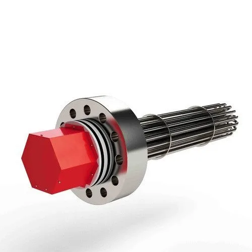
- Process Immersion Heaters|Tank Heaters
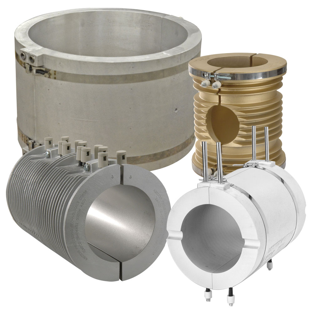
- Band Heaters
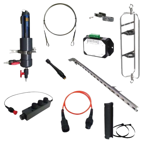
- Heat Tracers | Cable Heaters
- Silicon Rubber Heaters
- Heated Hose / Hose Pipe Heaters
- Etched Foil Heaters
View All
TEMPERATURE SENSORS & ACCESSORIES
- Thermocouples
- RTD Sensors
- Thermocouples Wires & Cables Accessories
- Temperature Transmitters
View All
- Technical
- Testimonial
- Contact us