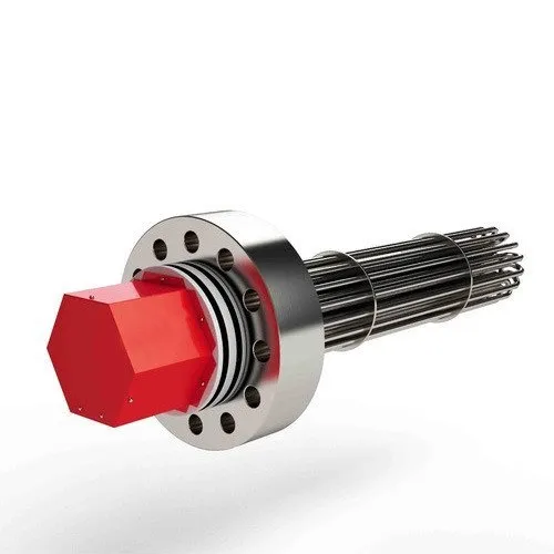
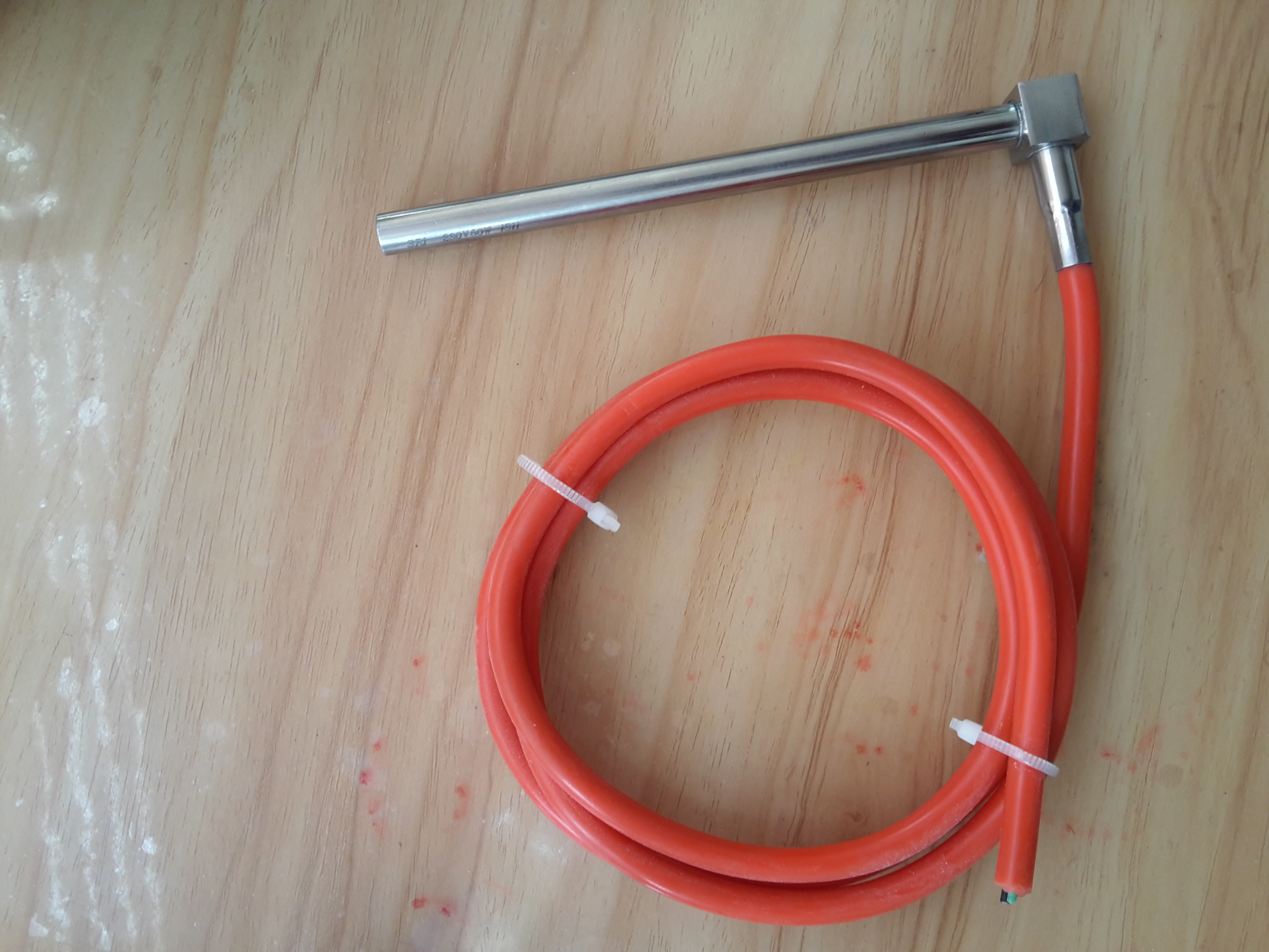
Matrusree Designs & Manufactures Cartridge Heater to suite a wide range of industrial applications as percustomer requirements. These also act as component heaters that are used to heat up many differentapplications. 
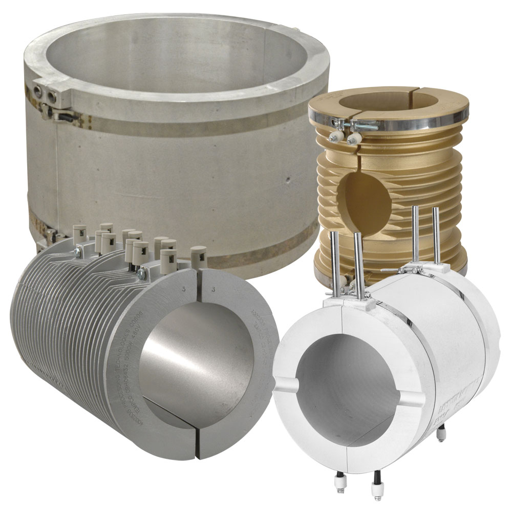
Primarily used in moulds& Dies heating by snug fit inside the holes or cavity of the mould andhelps to heat solids by reaching high temperatures.
Cartridge heaters have the versatility of being able to carry thermocouple inside to help control temperatures ofthe heater more accurately. Various diameters allow for it to be used in any cavity and can be custom designedwith any cold section. Lead wires extend from the end to your controls. 
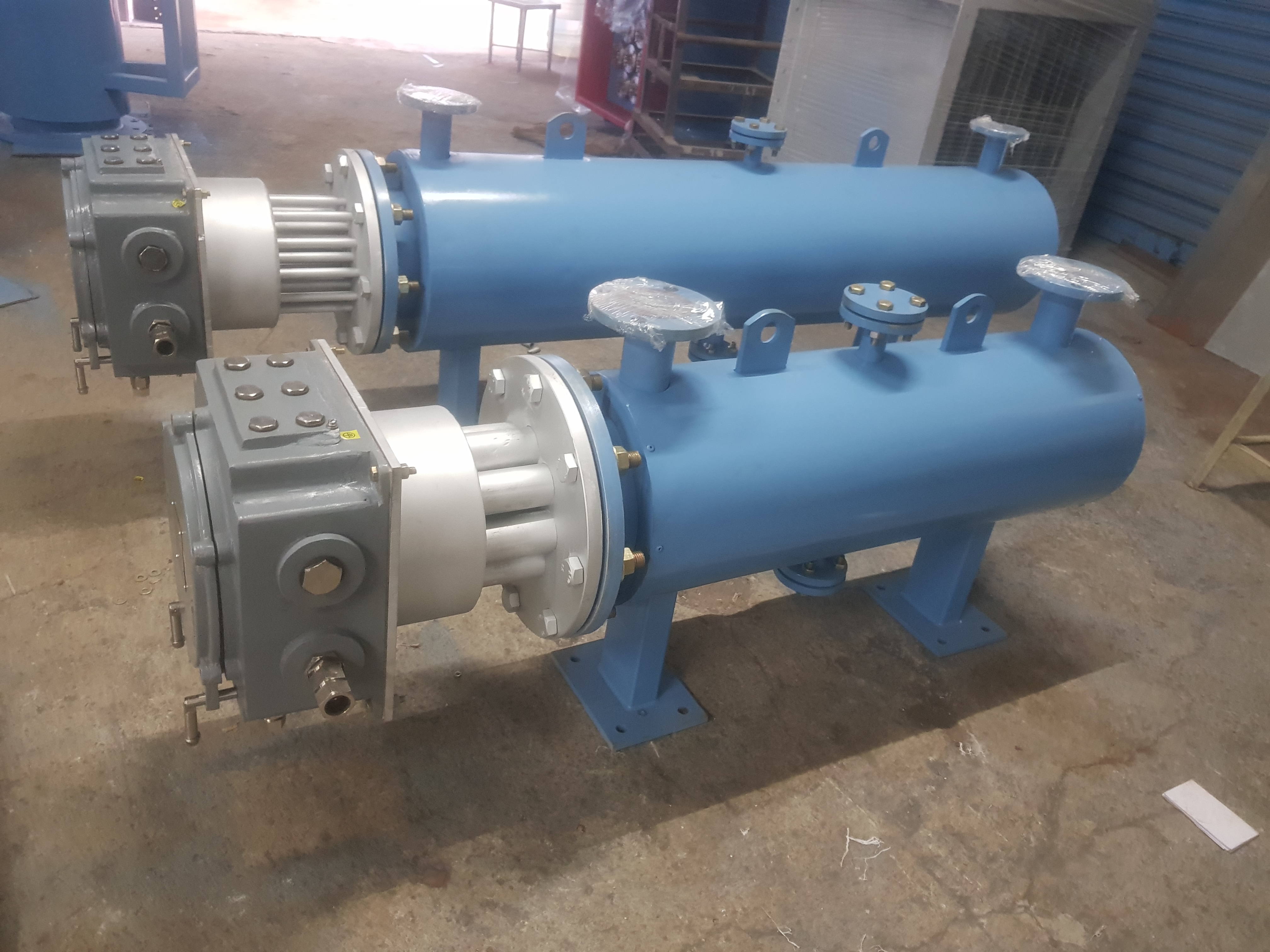
Depending on surface loading of thecartridge heaters elements we offer
LOW WATT DENSITY CARTRIDGE HEATER
The heater design consists of helically wound resistance coil made from High Temperature Resistance Wirewhich is evenly stretched and strung through holes in a cylindrical ceramic insulator. The element assembly isinserted into a SS300 series tubes. This alloy provides the best combination of physical strength and resistanceto heat oxidation. Then a Premium Quality Magnesium Oxide with Specially selected grain size and high purity (Mgo) is used to fillall remaining space inside the ceramic insulator to increase thermal conductivity, dielectric strength, andprovide longer operating heater life to the heater.
APPLICATIONS
v Built in Thermocouple 'J' or 'K' types designs available
v Rugged
& durable construction with excellent heat transfer capabilities
TECHNICAL FEATURES:
Features |
High Density |
Max.
Surface Load |
14
w/cm2 |
Wattage
Tolerance |
+/-10% |
Std.
Dia Range |
6.5mm to 25.4mm (1') |
Diameter
Tolerance |
-
0.02 mm to - 0.06 mm |
Std.
Length |
Min.
25mm |
Length
Tolerance |
+/-2mm |
Max.
Sheath Temperature |
700deg
C |
High Watt Density Cartridge Heaters Are Available In Above Standard Diameters & Sizes, Any Other Non Standard Intermediate Diameters Are Also Possible As Per Customer Requirement Standard Cable length - Fibreglass cable 300mm long.
Operating temperature of heater and fit size are major factors in determining the life expectancy of cartridge heaters. Select closest possible fit size for installing cartridge heaters.
Hole / Bore clearance is the gap between the heater O.D and the bore I.D should be very close. These close fits insure rapid heat transfer from the heater and also help keep the unit as cool as possible, which contributes to long life.
Enter the chart with either known variable, part fit in hole dimension or W/in2. Then find the application Temperature by reading up or over on the chart. If the fit of the heater in the hole dimension is not known, it is easily determined. Subtract the minimum diameter of the HD cartridge heater (nominal diameter minus tolerance) from the maximum hole diameter.
WATT DENSITY VS FIT IN HOLE SIZE FOR High Watt
Density CARTRIDGE HEATERS
MAXIMUM RECOMMENDED SURFACE LOAD |
|
High
Watt Density |
Max.150
W/Sq.inch Max.
25W/Sq.cm |
Medium
Watt Density |
Max.
65 W/Sq.inch Max.
10W/Sq.cm |
Low
Watt Density |
Max.
25W/Sq.inch Max.
4W/Sq.cm |
The graph shows the recommended maximum watt density for High Density Cartridge Heaters at different operating temperatures and fit, when the heater is installed in an oxidized mild steel block. The thermocouple is located 12.5 mm from the heater. When heating other materials, the data needs to be extrapolated based on the thermal conductivity of the material.
HOLE TOLERANCE |
< 80mm length + 0.1
mm |
81 to 200mm length +
0.15mm |
> 201 mm length +
0.2mm |
For cartridge heaters
with surface loads up to 20 W/cm2 the holemust be drilled according to ISA H7
with peak to valley height assmall as possible |
For higher load press fitting
is required |
Fit = Max.hole diameter
- Min.heaterdiamete |
To determine Fit :
Fit = Maximum Hole I.D - Minimum Heater O.D
Consider a Heater O.D = 12.5 mm (+/- 0.06mm std. tolerance)
Hole I.D = 12.6 mm (+/- 0.02mm hole tolerance)
Min heater O.D = 12.44 mm
Largest hole I.D = 12.62 mm
Fit = 12.62 - 12.44 = 0.18 mm (max permissible clearance)
HIGH WATT DENSITY CARTRIDGE HEATERS ARE AVAILABLE IN THE FOLLOWING DIAMETERS,
Anyother Intermediate diameter sizes are also manufactured as per customer specification.
Metric
Sizes mm |
5 |
6.5 |
8 |
10 |
12.5 |
16 |
20 |
22 |
25 |
Inch
Sizes mm |
3/16 |
1/4 |
5/16 |
3/8 |
1/2 |
5/8 |
3/4 |
7/8 |
1 |
Standard Cable length - Fibreglass cable 300mm long.
Terminal lead options as designated under
1. Fibre glass or Teflon wire crimped or welded to terminals
2. Fibre glass wire with SS metal braiding
3. Wires protected with SS or GI flexible conduits
4. All wires are available in straight or right angle exit
5. Drawing or sample required for special type terminals
HIGH WATT DENSITY CARTRIDGE HEATERS
Standard Termination
Options Available are
Important points to be observed when using High Watt Density
Cartridge Heaters
Ordering information - Please specify
1. Dia& length of the
heater
2. Wattage and Voltage
3. Type of termination
4. Cold zone length & hot
zone length
5. Quantity
6.
Any special option required like different termination or custom flanges please
send drawing or sample
Resistor wire is joined to the leads by placing each end into high temp lead wires which, upon crimping, affordsa positive and consistent junction.
Hi-Density cartridge heaters are manufactured in a complete range of standard physical dimensions, electricalratings and variety of lead terminations. In high-density cartridge heaters the resistance wire loops arepositioned as close as possible to the outside shell. Because the MgO powder insulation around these loops iscompacted by swaging and transformed into a very hard medium, heat transmission is very efficient. Cartridgesare usually supplied with lead wires.
The construction of high temperature High Watt Density cartridge heaters starts with aa premium grade high temperature resistance wire that is wound around a high purity magnesium oxide core with Numerically controlled machinery precision. It is inserted into a Stainless steel or Incoloy tubing locating the resistance wire close to the sheath. The core is centrally positioned within the tube and Machine Filled with Special Grade High Mgo. Nickel pins pass through the centre of the core making contact with the resistance wire at both ends. The whole is assembly is highly compacted by a swaging operation and thus ensuring excellent heat transfer to the external sheath. One end of the heater is closed with a welded metal end-disc and wire leads exit at the opposite end which is typically closed with a lava seal. A variety of wire leads and lead protection options are available. Heaters can be supplied with internal thermocouples, mounting fittings and many other options.